What are you looking for?
 author
The only penalty is that crimp contacts can be selected when a designated wire, contact barrel and tooling system meets the needs of your assembly. 3. Solder contacts — Choose these only when the connector is engineered for solder termination and you can regulate heat, solder application and wire support. There is no automatic better: it depends on the complete connection, its conditions of use and how it was built.
An all-important starting point for engineers and buyers comparing crimp vs solder contacts is the production drawing. Note that even a contact which fi ts the housing may not fit well with cable or assembly equipment as to the termination. Clear up those interfaces before signing off on the samples or asking for a production quote. Push those interfaces to closure before approving samples or asking for a production quote
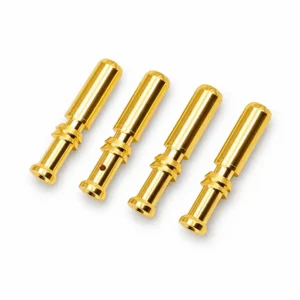
A crimp is a method of mechanically joining a conductor to the contact by deforming (compressively or radially squeezing) around/over the prepared wire. Both the contact geometry and the tool need to interact. JC standard crimp contacts are built around customer drawings including the barrel and mating features. JC day-to-day manufacturing custom crimp contacts around our customer’s drawings including the barrel and mating features.
Solder termination — Utilizes solder to attach the conductor to a compatible (suitable) termination feature. That feature takes the form of either a solder cup or some defined connection geometry, depending on design. JC offers solder contact choices based on size, Alloy Metal finishing and also mounting features. Just because you have a contact with only a hollow opening, this does not indicate that it is suitable for soldering.
Separate the wire connection from the mating interface. The pin or socket that engages the opposing connector performs a different function from the barrel or cup that accepts the wire. Both ends need their own dimensional and application checks.
| Decision point | Crimp termination | Solder termination |
| Contact design | Requires a barrel designed for the intended crimp process. | Requires a termination designed for soldering. |
| Process equipment | Specified tool, die or indenter, and positioning arrangement. | Suitable heating equipment, fixtures and soldering materials. |
| Main setup questions | Wire preparation, insertion, tool setting and crimp location. | Wire fit, heat access, solder application and process limits. |
| Inspection basis | Contact-specific geometry, workmanship and agreed mechanical checks. | Contact-specific workmanship, solder-joint condition and agreed checks. |
| Production planning | Assess tooling availability, changeovers and maintenance. | Assess operator access, fixturing, heating and inspection time. |
| Approval decision | Validate the actual wire–contact–tool combination. | Validate the actual wire–contact–soldering process combination. |
Do NOT use the table to declare a general advantage in reliability or cost for either method; instead, find what must be established from these two mechanisms. As an example, having a crimp tool does not indicate that its die or locator is suitable for one new contact. Similarly, an existing soldering station fails to place the right process on yet another mass or finish of contact.
Send the wire part number, conductor size (AWG), strand construction,conductor material or coating and insulation OD. Where applicable, include the preparation requirements and an actual cable sample (Example: Nominal wire gauge is a helpful but partial description of the cable. A wire gauge is just a nominal (rough) description but does not describe the whole cable
Wire size is defined in sections based on maximum and minimum tolerance for strand construction and insulation dimensions as described by The Molex Quality Crimping Handbook. This is not defined by the general guidance that helps to frame your reviews; it must be established using The Application Specification of the chosen contact. Its high-level guidance structures the review; actual acceptance limits must be defined in a contact’s application specification
For a solder cup, verify the prepared conductor fits and can be reliably placed. For a crimp barrel, verify the desired wire range and if its preparation meets the contact and tooling requirements. Do not solve mismatch removing strands or a change undocumented in contact. Misalignment is not solved by removing strands or modifying the contact undocumented.
Check the insertion depth, embracing shoulders or grooves and mating limits and space behind a connector Incorporate backshell, seal and cable-support requirements if appropriate. Only the triggering at dB or, with other words Triggering and Access could be set. A termination change can impact a vehicle’s service as long as the front of contact remains consistent
When comparing precision pins and sockets, identify which dimensions control mating, which control retention, and which control wire termination. This distinction makes a drawing review more useful than comparing product photographs.
Crimping is a consideration if the proper tooling exists (and that the assembly team can be highly repeatable in its setup). Before selecting it, find out who will provide or define the tooling: Who locates the contact? How if operators need to check setup after a changeover. Ask about where the tooling will be supplied, how to identify that contact and verify with operators regarding the setup after a changeover before choosing it.
TE dotated wire, TE likes to point out proper tooling (with their personalized closed-barrel crimping guide), a suitable terminal with prepped stranding on the ready judge placed personnel as well. They are practical review questions, not proof that one tool is compatible with every closed-barrel contact. These are helpful review questions — not proof that one tool works at every closed-barrel contact.
The intended crimp method should be identified in the drawing and application instructions Do not just bring an acceptance interface dimension from another terminal design because they’re both called crimp contacts. Use dimensional, visual criteria and pull-test requirements to define the checks for contact selection. Checks for the selected contact — this is where you define everything required (dimension measurements, visual details and pull test)
Finally, note that wire retention is distinct from electrical performance. A pull test addresses just a mechanical issue, it does not define contact resistance on its own nor temperature rise or service performance. Independent specifications on the application tests to be agreed with set conditions and acceptance criteria Settle the application tests independently with defined conditions and acceptance criteria
Soldering is an option when the joint design allows it and access control from both heating sides and inspection are guaranteed. Consider termination shape, material and finish in addition to the solder alloy, flux list of equipment, work instructions etc. If you want to do a review, its described shape and size of end termination together with which type of solder alloy is used for lead-free electronics assembly further details on component or equipment having the right material thicknesses where they are located.
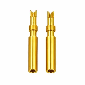
Soldered contact pins require these defined process with enough assemble location ([474[13])(435). Examine how this wire will be secured, extreme areas of heat input or output zone and if any surrounding insulation or connector cutouts act as limits. Determine the allowed temperature and exposure time from relevant component /process documentation vs. copying a general solder reflow setting.
As a concrete implementation of contact-specific instructions, Harwin’s Kona assembly sheet tackles wire prep and the filling and cleaning of cups. Those instructions are applicable to its named contacts; they demonstrate why a custom JC contact must have individually negotiated assembly parameters. Those instructions are for its named contacts; they show why a custom JC contact requires an agreed assembly be stated.
While planning the joint, plan the inspection. Define acceptable soldering, insulation and cleanliness requirements. Add cable management into the assembly drawing, so termination is not relied upon for holding back cables. Add cable support in the assembly drawing so that it is understood that termination should not be relied on to manage cable movement
A useful quotation package connects the component drawing to the way the assembly will be made. Include:
Last, if working with custom parts then describe how you will make and test the termination feature. As such, JC’s legitimate CNC turning capabilities represent an appropriate touchpoint in the context of reviewing turned contact geometry. Please agree on the final drawing and acceptance plan before taking your samples as production baselines. Final drawings and acceptance plan mutually agreed upon before treating a sample as production reference
Simply how it terminates is not evidence of vibration performance. Consider the full assembly including wire support, contact retention, connector mounting and environmental factors. Choose a reproducible approach then validate it under the agreed conditions app. Do not consider either crimp or solder qualification as a replacement for the other.
Never add solder as a makeshift fix for an unacceptable crimp. Which requires design review the assembly process changes. Stick to the appropriate reworking or upgrading process. If a design parametrically mixes crimping with solder, its instructions and validation must deal unambiguously with that mix. If a design purposely combines crimping with solder, the instructions and validation have to explicitly cover that combination
You can only check for compatibility after that. Contacts that look similar may vary in retention features, mating position or rear clearance. Validate the housing interface and configuration, as well as wire splices need. Approval of a substitution requires more than matching outside diameter. A matching Outside Diameter in itself is not sufficient to approve a substitution
You can then select a contact, and an process together to agree on how you want the final assembly. Please send your contact drawing and wire specification for JC to review the geometry/material/finish & termination features that are needed by you. Always add how you want to assemble it so that we start with the connection which you need to build.

Choose Jingcheng for one-stop precision connector solutions. Automated production reduces costs, while strict quality control guarantees performance. Enjoy higher precision, faster delivery, and a brand-new cooperative experience with superior cost-performance.