What are you looking for?
 author
Specify custom PCB pins together with the board interface and assembly method. Start with the finished hole dimensions, pin geometry, board thickness and intended mounting process. Then check seating height, alignment and access for assembly. A pin that enters one sample board is not, by itself, evidence that the design will assemble consistently across production tolerances.
For a new board connection, the first decision is how the pin will be secured and how the electrical connection will be made. A soldered through-hole tail and a designed press-fit section require different interface definitions. JC’s custom PCB contacts include pin and socket configurations with board mounting features made to customer drawings. The following checks help turn that drawing into an assembly requirement that the pin supplier, PCB fabricator and assembler can review together.
“Through-hole” describes where a terminal goes; it does not fully specify how that terminal is retained. Identify whether the design uses a soldered tail, a qualified press-fit interface or another documented retention arrangement. Record whether the mounting hole is plated and what role it plays in the circuit.
For a soldered tail, review insertion clearance and the requirements of the selected soldering process. For a press-fit design, review the defined insertion zone and its matching hole specification. Do not turn a solder-tail pin into a press-fit design simply by reducing the hole diameter.
TE’s press-fit technology overview distinguishes solid and compliant press-in zones and describes the pin and plated-through hole as a system. That principle is useful here: the word “press-fit” does not establish a universal geometry, hole tolerance or insertion force. Confirm which construction the proposed custom part uses and obtain its application requirements.
A drill diameter and a finished plated-hole diameter describe different stages of PCB fabrication. Tell the board fabricator which finished interface the assembly needs, and ask it to confirm the manufacturing specification required to achieve it. For a press-fit connection, the review may also need the hole plating and board construction requirements specified for that pin system.
For a simple round solder tail in a round hole, a useful dimensional screening calculation is minimum diametral clearance: minimum finished hole diameter minus maximum finished pin diameter. This checks one possible source of interference. It does not define an acceptable solder gap or prove that the entire assembly will fit.
Use the finished pin dimensions, including applicable plating, and identify the section that actually passes through the board. A shoulder, transition or forming feature can be larger than the nominal tail. For a non-round section, review the full cross-sectional envelope and orientation rather than treating its width as a round diameter.
| Interface to review | Information to provide | Question to resolve |
| Hole and pin | Finished hole limits; finished pin section and limits. | Can the intended fit be achieved at the dimensional extremes? |
| Board thickness | Thickness range; seating surface; tail length. | Is there enough engagement or protrusion without excess projection? |
| Hole pattern | Pitch, positional tolerances and assembly datums. | Will the complete pin pattern align with the board? |
| Mounting feature | Shoulder, interference zone or other retention detail. | Which feature sets the insertion depth and supports the load? |
| Process access | Tool approach, board support and nearby components. | Can the part be installed and inspected in the intended sequence? |
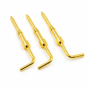
Overall pin length is not enough to define an installed contact. Mark the intended board seating surface and show the required projection on each side. For a bent pin, also identify bend orientation and the reference surfaces used to inspect it.
A thicker board can reduce the tail projection available below it when the seating position remains fixed. A thinner board can leave more exposed length. Review both conditions against soldering access, underside component clearance and the enclosure. For press-fit parts, check where the specified insertion zone sits within the board thickness at the approved seating depth.
The mating end needs a separate check. If another connector or board engages the pin, establish the permitted mating position from the assembled stack, including supports and spacers. JC’s pin and socket range provides examples of contact configurations; compatibility still depends on the selected mating parts and their drawings.
A single pin may enter a single hole while a complete row fails to align. Review pin spacing, hole positions, perpendicularity where applicable, and the datums used by the component and PCB drawings. Confirm whether pins are installed individually or held by a carrier, housing or fixture during insertion.
For example, a fixture that holds several pins at a fixed pitch must be checked against the PCB pattern as an assembly. Individually acceptable diameters do not resolve accumulated positional mismatch. Use representative boards and the intended fixture during sample evaluation, and record the board and component revisions.
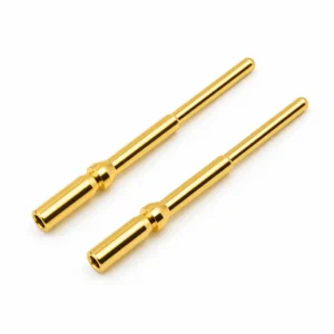
For turned custom PCB pins, distinguish the features controlled during machining from those established by bending or final assembly. Discuss these interfaces when reviewing JC’s CNC turning capabilities, so the drawing identifies which finished dimensions matter to board installation.
Ask the assembler to review the proposed pin before the board layout is frozen. Identify the tool approach, the surfaces available for applying load, and the support required beneath the board. Check whether adjacent components block insertion, soldering or inspection after earlier operations are complete.
For soldered mounting, agree on the process, component thermal limits, positioning method and acceptance criteria. For press-fit mounting, agree on the specified tooling, seating depth and any force monitoring or inspection requirements. Do not assign a generic insertion force or soldering temperature to a custom geometry.
Sample evaluation should answer several distinct questions:
A continuity result alone does not establish current capacity, temperature rise or durability. Define any application testing separately. During manufacturing and service review with JC, distinguish component inspection from board assembly validation and agree who will provide each record.
Send the component drawing and revision together with the relevant PCB fabrication and assembly details. Include the finished hole specification, board thickness range, hole pattern, mounting method, required installed height and mating interface. Add material and plating requirements, planned quantities and a sample board or fixture information where available.
If the board is already fixed, state that constraint at the start. If both the board and pin can change, identify which dimensions remain open for joint review. This avoids approving a pin around an assumed hole size that the PCB supplier has never accepted.
It can support an initial discussion, but it is insufficient for approving the fit. Provide finished hole limits, pin dimensions and the intended mounting method. Include board thickness and pattern information when they affect installation. Clearly distinguish a preliminary quotation from approval of a complete board interface.
Only when the part design and application requirements explicitly support both methods. A mounting description or photograph is not enough to approve a substitution. Review the insertion feature, board specification, tooling and acceptance criteria for each proposed process before changing the assembly method.
Stop and compare the actual pin, finished hole and pattern measurements with the agreed specifications. Check seating features and alignment before modifying either part. Increasing force or enlarging a plated hole informally can change the interface being evaluated and invalidate the original sample comparison.
The useful output of a design review is an agreed pin, board and assembly specification. Send JC your PCB pin drawing and board requirements to review the mounting geometry, material, plating and mating features. Include the installation method and acceptance criteria so sample evaluation tests the connection you intend to manufacture.

Choose Jingcheng for one-stop precision connector solutions. Automated production reduces costs, while strict quality control guarantees performance. Enjoy higher precision, faster delivery, and a brand-new cooperative experience with superior cost-performance.