What are you looking for?
 author
Before ordering solder contact pins, define the wire, termination geometry, material and finish, assembly access, and acceptance criteria together. A drawing that gives only overall length and mating diameter leaves important assembly decisions unresolved. The soldering team also needs to know how the conductor is positioned, how the joint can be heated and inspected, and how the cable is supported after assembly.
This guide addresses the information needed after a solder termination has been selected. JC’s custom solder contacts can be manufactured to customer drawings with specified dimensions, materials, plating and termination features. A complete enquiry connects those component requirements to the intended wire assembly, rather than treating the contact as an isolated metal part.
Divide the drawing into functional areas: the mating end, the housing retention features and the solder termination. Identify the dimensions and reference surfaces that control each area. This helps prevent a change intended to improve solder access from unintentionally changing the installed contact position.
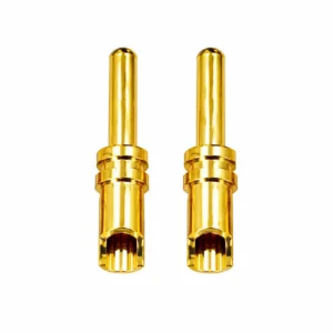
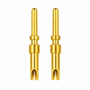
Where the design uses a solder cup, show the opening, depth and relevant internal geometry. Include any slot, cutaway or other access feature that is part of the design. State how far the prepared conductor should enter and which feature establishes that position. A product photograph cannot supply these dimensions or establish an acceptable joint.
Review the mating end with its intended counterpart. JC’s pin and socket contact range provides examples of contact configurations, but visual similarity does not establish compatibility. Keep the mating requirement separate from the wire termination requirement, even when both features are machined into one part.
Provide the wire part number, conductor size, strand construction, conductor finish and insulation outside diameter. Include the proposed strip length and any preparation steps. If pre-tinning is part of the approved process, assess the prepared conductor rather than assuming its dimensions remain identical to those of bare strands.
A useful sample review uses the actual production wire and the intended preparation equipment. Check whether the conductor can reach its specified position without missing strands, interference from insulation or an undocumented change to the wire. Do not approve an oversized conductor by cutting away strands to make it fit.
Different wire constructions may need separate review even when their nominal size is the same. Record approved wire alternatives explicitly. An informal change in cable supply can otherwise leave the assembler working with a combination that was never evaluated.
| Design input | What to provide | What the review should resolve |
| Prepared conductor | Wire specification, strip length and preparation method. | Fit and repeatable positioning in the termination. |
| Solder feature | Dimensioned cup or other termination geometry. | Wire entry, heating access and joint visibility. |
| Installed contact | Housing interface and assembly sequence. | Clearance for tools, adjacent contacts and insulation. |
| Surface specification | Base material, plating system and controlled regions. | Suitability for mating and the intended soldering process. |
| Cable support | Routing, support position and permitted movement. | How service loads are managed beyond the joint. |
Specify the base material and finish rather than describing a contact only as gold-colored or silver-colored. Where different regions have different requirements, identify them on the drawing. The mating surface and the solder termination should each be reviewed against their own function.
Ask the contact supplier and assembler to resolve solderability requirements, plating coverage, handling and storage conditions before samples are approved. Avoid selecting a finish solely from its appearance. Likewise, do not substitute a different finish on a repeat order without checking whether it changes the assembly process or the mating interface.
For turned solder contact pins, review the manufacturing drawing with the finished condition in mind. Relevant dimensions should state whether they apply before or after plating. JC’s CNC turning capabilities are a starting point for discussing the part geometry; the final drawing must still define the project’s material, surface and inspection requirements.
Review the contact in the assembly position in which soldering will actually occur. Show the housing, nearby terminals, insulation and any sleeves that will already be fitted. Check the approach for the heating tool and solder feed, as well as the view needed to inspect the joint.
Assembly order matters. A sleeve that must slide over the cable before soldering may be impossible to install afterward. A rear cover may block access once neighbouring contacts are populated. Resolve these sequence questions in the sample build, not after all parts have been released for production.
The soldering procedure should identify the solder alloy, flux, equipment, fixtures and applicable thermal limits. Establish heating conditions from the selected materials, components and validated process. A generic soldering temperature is not a specification for every custom contact.
For an example of product-specific instructions, Harwin’s Kona contact assembly sheet addresses conductor preparation, solder-cup filling and cleaning. Its instructions apply to the named Harwin contacts. The lesson for a custom design is to document the equivalent process decisions, not to copy another contact’s dimensions or assembly settings.
Show how the cable is routed and supported after termination. Identify the expected movement and the parts intended to carry handling loads. Do not leave the solder joint as an unspecified substitute for cable support. Check that the support arrangement can be assembled without disturbing the contact’s seating position.
Agree on the inspection criteria before the sample build. These should cover the applicable joint condition, conductor position, insulation condition, cleanliness and any prohibited solder on adjacent features. Specify how hard-to-see areas will be assessed. “Looks acceptable” is not a repeatable acceptance instruction.
Separate component inspection from assembly testing. A dimensional report for a loose pin does not prove the quality of the completed wire joint. A continuity check does not by itself establish temperature rise, mechanical durability or suitability for the intended environment. Define additional tests and acceptance limits according to the application, without assuming they are included in a standard component quotation.
During manufacturing and service discussions with JC, identify which records the component supplier will provide and which the assembler or product team will produce. Link results to the drawing revision, contact lot, wire specification and process used for the samples.
Before releasing solder contact pins, collect the agreed component drawing, wire specification and assembly instruction in one controlled package. Include the sample findings and any changes made during evaluation. An approved sample is useful only when the supplier and assembler know which version it represents.
Record the following decisions:
For example, if a revised cup makes tool access easier, check whether conductor positioning, wall geometry or overall clearance also changed. Record the accepted revision rather than relying on a verbal instruction to use the latest sample.
No. Provide the actual wire construction and prepared conductor requirements, along with the cup geometry and intended insertion position. Nominal wire size helps start the discussion, but sample fit and a defined assembly process are needed to approve a specific wire and contact combination.
No. A hollow opening does not establish its intended function or suitability for soldering. Confirm the termination design, material, finish and assembly requirements. Do not treat a socket’s mating opening or an ordinary crimp barrel as a solder cup without explicit design approval.
Send the current contact drawing, wire specification and expected assembly sequence. Include material and plating requirements, relevant housing constraints, quantities and the evidence needed for approval. A production wire sample and an assembly view can resolve questions that an isolated contact drawing leaves open.
Share your solder contact drawing and assembly inputs with JC to review the required geometry, material and finish. Include the wire and planned soldering method so the sample discussion can address the connection you will build, inspect and reproduce.

Choose Jingcheng for one-stop precision connector solutions. Automated production reduces costs, while strict quality control guarantees performance. Enjoy higher precision, faster delivery, and a brand-new cooperative experience with superior cost-performance.